Dolly Project
My seemingly unending project to build a simple camera dolly for doing timelapses and whatnot.
30 Apr 2011
Slide
The Igus slide for my time-lapse/video dolly project arrived yesterday...
19 May 2012
Mo-Co Dolly, Rough Assembly
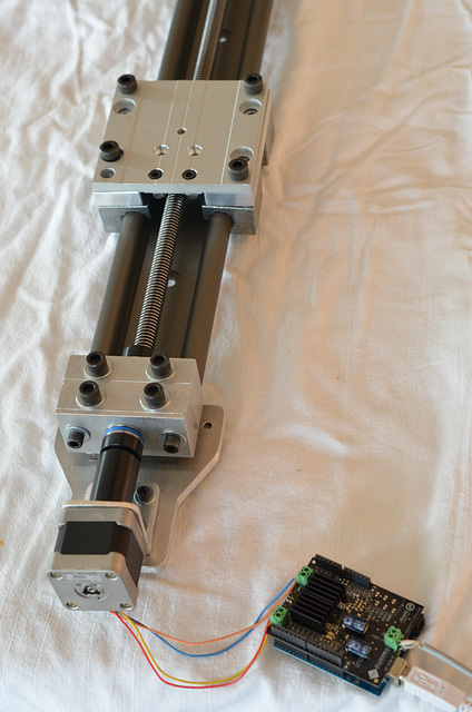
A test assembly of the in-work motion control dolly. Not everything is bolted down tightly yet, this was just to see if it would all go together, and when it did, if it would run.
And run it did.
Took a little more power to drive the carriage than I thought it would, but the motor shield on the Arduino didn't even get noticeably above room temperature (unlike the other one whose bridge I burned out with no load on the motor -- oops).
The Delrin coupling seems to be a tiny bit off-centered, but it's just a fit-up problem -- close enough to proceed with finishing the assorted aluminum bits and wiring up the limit switches.
04 Sep 2012
Switchcraft
Limit switch brackets, the last pieces I (think I) needed to cut for the motion control slider, ready to prime and paint.
(Oops - not quite ready, as the brackets for the tailstock caused an interference and had to be cut down a bit.)
09 Sep 2012
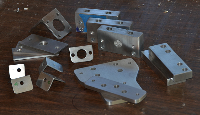
Ready to Clean and Paint
All of the aluminum parts, sanded and buffed and ready to be solvent wiped prior to painting.
09 Sep 2012
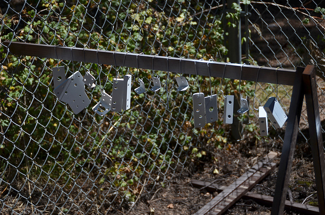
Primed
After spraying with aluminum primer. The parts will be satin black to minimize reflections, but the primer was only available in white
30 Sep 2012
Work In Progress: MoCo Dolly
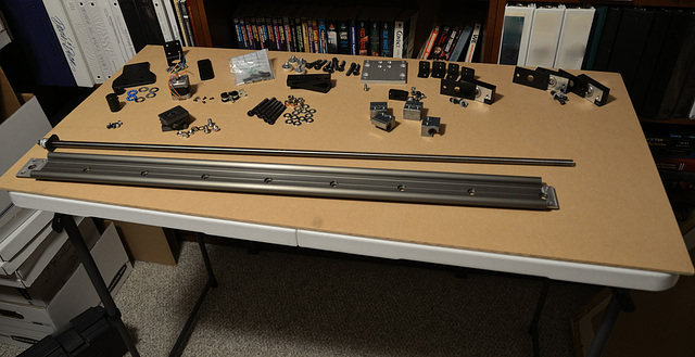
All of the parts (or so I thought at the time), individually laid out and ready for assembly.
Some additional fastener purchases proved necessary during the build. Oops.
30 Sep 2012
Work In Progress: MoCo Dolly
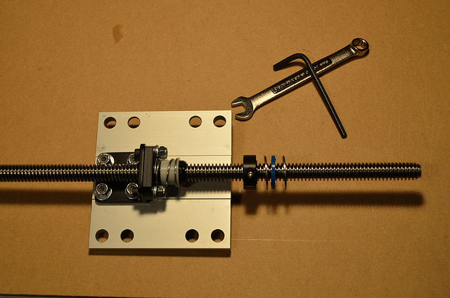
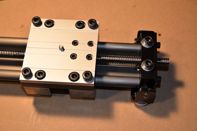
The underside of the modified carriage, showing the anti-backlash Acme drive nut and its mounting bracket, one of the Acme lock collars, and one of the thrust bearings. Note that the off-center position of the bracket (shifted tailward) permits the carriage to run over the lock collar and thrust bearing at the head end, so that the carriage doesn't have to stop two inches short.
This is proving to be the locus of some trouble at the moment. Due to a slight (but non-negligable) runout error in the Acme rod, the drive nut drives the carriage in a helical motion (up and down and right and left as it goes), making the camera wobble. Need to tighten up the sliding bearings and work some of the runout out of the rod...
The runout problem was subsequently addressed by mounting the drive nut to a new bracket which slides along the base of the IGUS slider, and drags the up-standing leg on the black bracket (cut down to a 4mm tab) as it goes. The tab fits into a gap on the new bracket which is small enough to not allow any noticeable backlash, but loose enough that the wobble from the Acme rod isn't transmitted to the carriage (and to make it more gearheady, the tab is tapered and rounded slightly so that there is theoretically only ever point-contact between it and the new bracket). The original problem boiled down to the nut transmitting off-axis translations to the carriage - the new arrangement only permits it to apply force in the axis direction. Problem solved.
Now, if I were an uber-gearhead, I would have drilled a hole in the little tab and press-fit a ball bearing in it to ensure there was only ever point contact...
04 Oct 2012
Work In Progress: MoCo Dolly
The head bearing, coupler, stepper motor, and assorted bracketry and mechanical bits. The assembly worked at this point, but I hadn't finished wiring in the limit switches or bundling the wiring together. One twisted wire on either side of the bearing block actually runs through the inside of the slide to the limit switches flanking the tail bearing, the other runs through the first head bearing, out the bottom of the second, and to the head-end limit switches. The idea is to conceal as much of the wiring as possible.
After the wiring was completed, the wiring was bundled together using heatshrink tubing and tied down with P-clamps mounted using two of the motor bracket bolts (seen under the coupling).
Each end has two redundant limit switches, each of which can be read by the microcontroller independently. A quad OR gate also triggers an interrupt on the microcontroller if any single switch is closed, resulting in an immediate hard-stop of the carriage.
And yes, I know the motor hangs out, unprotected, beyond the plate. No excuse, just bad design on my part. I had plenty of aluminum - there's no reason I couldn't have made that plate another 35mm longer.
04 Oct 2012
Work In Progress: MoCo Dolly
The (loosely) assembled carriage and tail bearing, with limit switches installed and wired in. The wiring runs through the slide rails (which are hollow) and out through concealed mouseholes in the underside of the tail bearing block...all neatly tucked away.
The contact rollers on the limit switches can be seen peeking just past the switch brackets. It may look like the carriage would crash before actuating the switches, but it reliably contacts both switches and stops with about 1/16" to spare at either end.
Jump to top
RSS feed- Latest items - Subscribe to the latest items added to this album
- ipernity © 2007-2025
- Help & Contact
|
Club news
|
About ipernity
|
History |
ipernity Club & Prices |
Guide of good conduct
Donate | Group guidelines | Privacy policy | Terms of use | Statutes | In memoria -
Facebook
Twitter


